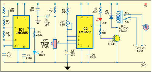
Circuit Diagram Timer Switch
Circuit timer switch relay 12v bc547 based transistor using diagram circuits working volt explanation Timer switch control Adjustable auto on off delay timer circuit using 555 ic
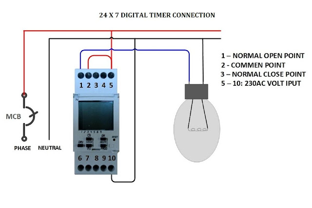
Digital Timer Control Switch Connection and Working
Timer stack install 12v relay based timer switch circuit using bc547 transistor Timer wiring switch diagram switching completed below
Switch wiring
Digital timer control switch connection and workingCircuit diagram timer switch seekic control Timer switchSimple delay timer circuits explained.
Need help wiring a 3-way honeywell digital timer switchWiring for my timer switch Touch-free timer switchSwitch wiring diagram light mobile timer leviton wall install house wire electrical wires switches installing three replacing lcd trying info.
Timer switch touch diagram circuit fig
Bathroom fan timer switch wiring diagram : combo switch fan light 110vTimer delay 555 circuit off using ic auto adjustable simple schematic relay module output dc inline loads appliances heavy ac Delay timer circuits circuit simple electronic explained diagram homemade seconds schematics electronics step two using make projects sequential few transistorsTimer switch connection diagram.
Wiring diagram switch timer way honeywell damper need help digital temp trol zone leviton light decora switches wire stack relayTimer light connection street setting Street light timer setting & connection with practicalSwitch timer diagram two electrical.

Timer switch circuit diagram
Trying to install leviton in-wall lcd timer switchTimer digital control switch connection diagram connect contactor working .
.


